Light Dependent Resistor
For this exercise, we will be going to use the Light Dependent Resistor (LDR) to trigger the RGB LED! We can make use of the LDR to turn on the RGB LED when the environment is dark, and use the potentiometer to control the colour of the LED!
Table of Contents
About the Component
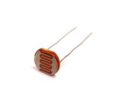
The Light Dependent Resistor (LDR/Photoresistor) is a type of resistor that reacts with light. When the amount of light it detects changes, the resistance changes. However, as there are many types of LDRs around, the way they change resistance with the amount of light would be different.
As the LDR reacts to the amount of light it receives, it is very useful as automatic brightness control on your laptops and mobile devices.
Reading LDR value
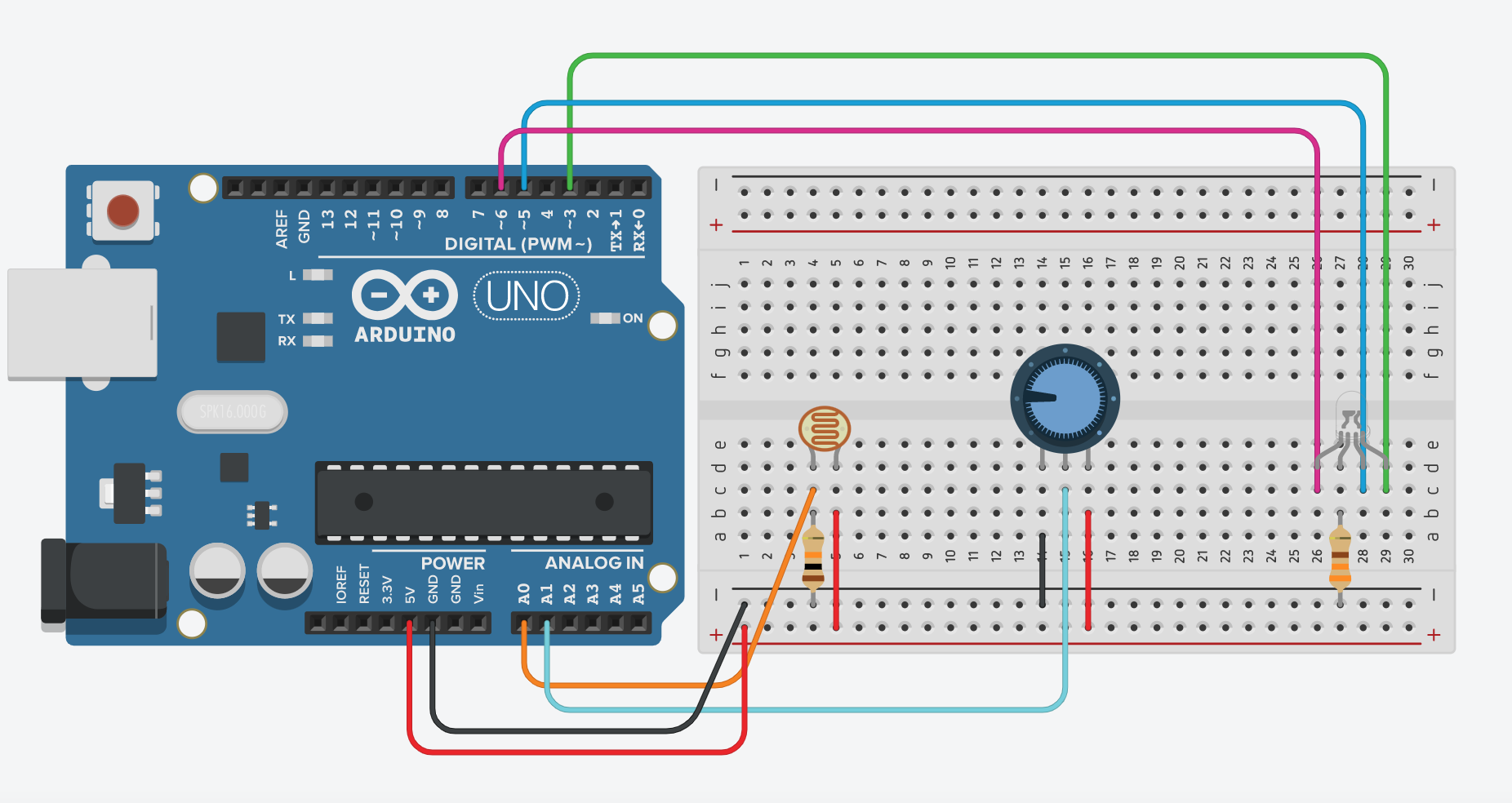
Let's create a new circuit on TinkerCAD like this:
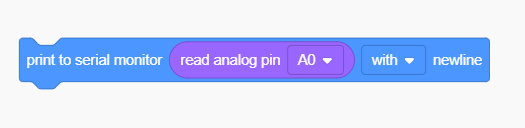
We will read the value from the LDR and output it on the serial monitor:
When running the simulation, open up the serial monitor. The result should look something like this:
While I change the light intensity of the LDR, the readings also change.
Calibration of the sensor
As the sensor has multiple variations, let's check yours out! Construct the circuit on your SSTuino!
Warning: To prevent damage to your Learning Device or your components, please do not connect the SSTuino to your LD or power supply when you are wiring up your circuit.
After you are done uploading the code, open the serial monitor. Now note down the value when the room is lit. Afterwards, turn off the lights in the room and note down the value again. We will need this data afterwards to tell when to turn on the RGB LED.
Tip: If the lights in the room are unable to be turned off, you can use your hands to cover the LDR. Similarly, if your environment is originally dark, you can use the torch from your mobile device to shine at it.
Control RGB LED
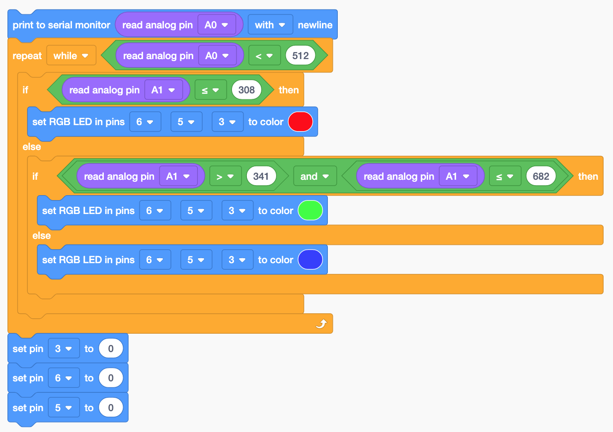
Now let us make the sensor useful! Make it such that the LED will light up when the environment darkens, and you can use the potentiometer to control the colour. To do so, we edit our code to something like this:
Tip: Use the average of your bright and dark value and input it inside the area (Read analog pin A0 < 512)
Afterwards, upload the code to the SSTuino. It should look like this:
Let's share your work! Record and post a video onto Instagram with the hashtag #sstuino!
If you have other ideas on how to control the RGB LED, please try them out and share them with your peers too!