TinkerCAD Introduction
Let us create our first virtual circuit! Circuit Simulation is a great tool to test out your circuit design before assembling it in real life. This helps to reduce the possibility of your components being damaged due to an incorrect circuit design.
Tip: As we will be progressing towards tinkering and creating a circuit, please do not connect the circuit/project to power before completing it. This lowers the risk of a component failure due to an improperly constructed circuit. 🙂
For our virtual circuits, we will be using TinkerCAD! It is one of the most popular classroom tools for creating simple designs from scratch. It is also a simple to use online 3D design and prototyping program.
Let us set up TinkerCAD and have fun with a mini project!
Sign in to TinkerCAD
Signing in to TinkerCAD is very simple! Simply head over to the website:
Click on Join Now

Click on Create a personal account, and Sign in with Google. Proceed to sign up with your SST Gmail account.


Create a Circuit
There are a lot of functions inside TinkerCAD! However, for the purposes of the SSTuino, we are going to use the "Circuits" function. Click on "Circuits" on the sidebar and click on "Create new Circuit".
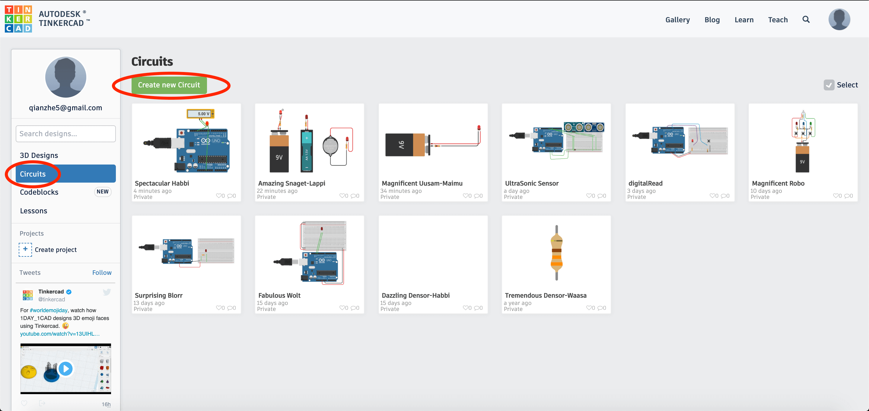
Tip: It is a very good habit to create a new circuit after you have finished your previous tutorial, instead of overwriting the current circuit. That way, you would be able to refer to previous tutorials done when you need help with your future projects.
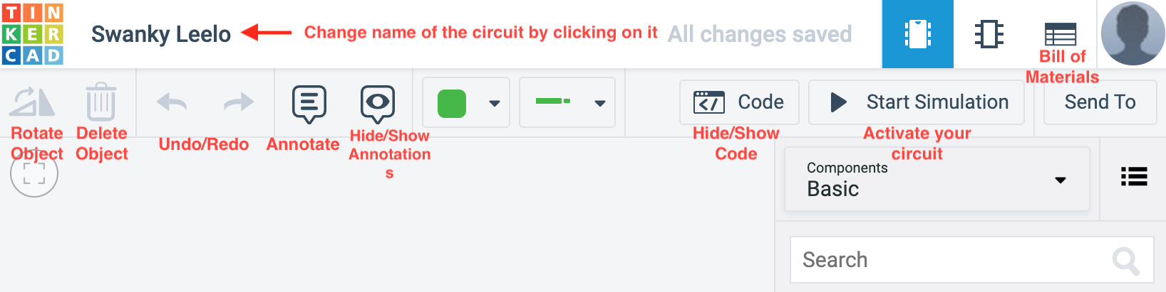
After you have created the new circuit, it should look like this. We have also included a legend on the interface of the TinkerCAD Circuits function.
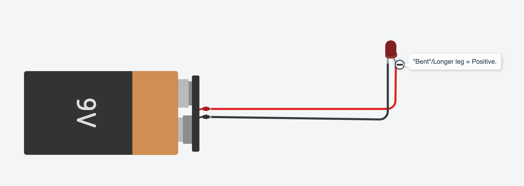
Let us bring out a 9V battery then connect it as follows. After you have connected the circuit, click on Start Simulation on the top right-hand corner of the website. You will notice that the LED immediately "explodes". 🤭

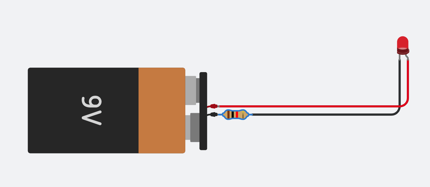
The LED burns as there is no resistor used to limit the flow of the current. Instead, connect a resistor like this. With the resistor attached, the LED lights up without burning up. 🙂 Try this with different resistor values. What kind of changes would happen here?
Now, let us try this out using different types of batteries. TinkerCAD mainly provides 3 types of batteries: 9V, 3V and 1.5V. Connect your circuit up as shown. The next picture illustrates when you start the simulation:
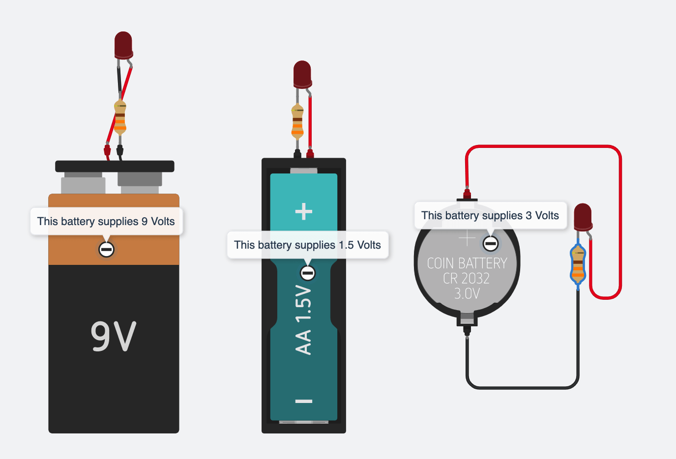
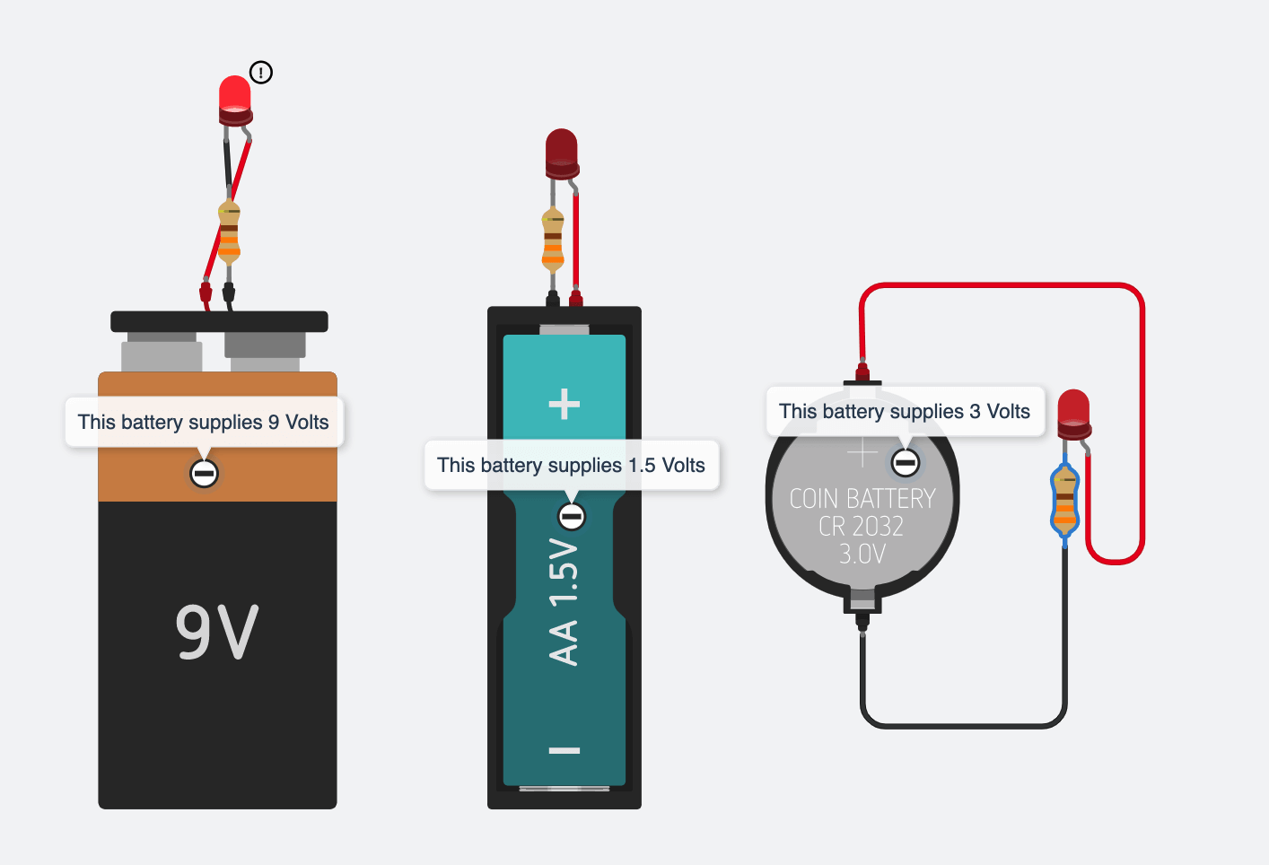
Why would this happen? This is because LEDs have a minimum voltage to light up. If you look at the spec sheet located here:
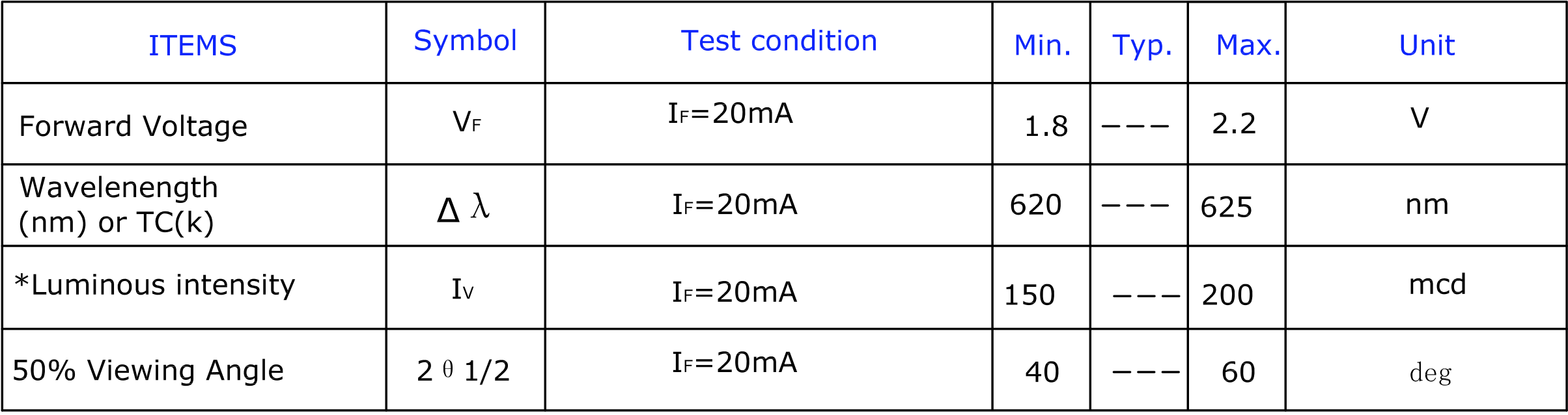
The 1.5V battery would be barely able to light up the circuit, and only the 2 other battery types will be able to light up the LED.