Pull-up resistors and If/Else Statements
In this tutorial, we will learn about pull up resistors, and use push buttons to control lighting.
Table of Contents
Pull-up resistors
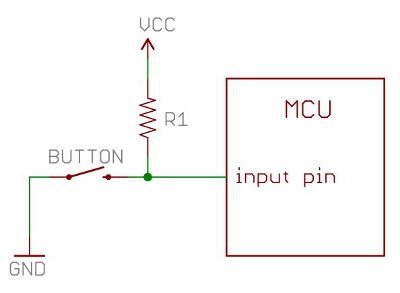
Pull-up resistors are found in digital logic devices and microcontrollers. When a pin in say, the SSTuino is connected as an input and tries to read the state of the pin, it is very difficult to determine whether the pin is actually high or low, due to a lot of factors such as noise in the circuit. This effect is referred to as floating.
To eliminate this, we will place a pull-up resistor to ensure that the pin is either in its HIGH or LOW state, while using a little bit of current. Pull-up resistors are usually used on buttons and switches where there is a possibility of signal noise.
Buttons and If/Else Statement
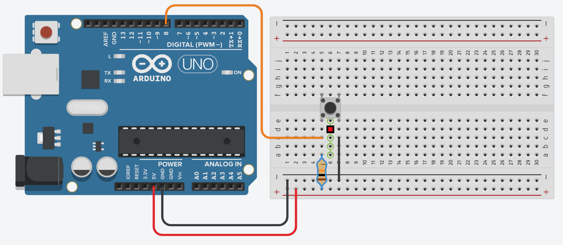
We are going to read very simple data from a push button, to know whether it has been pressed or not. Set up your circuit as shown:
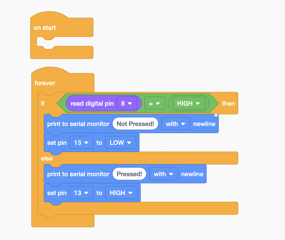
Next, go to the coding section and then program it like this:
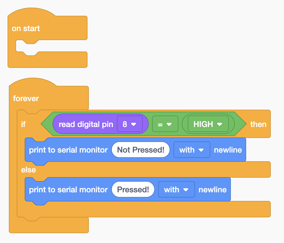
What this code does is that the Arduino would wait for the button to be pressed. If the button is not pressed, it would output "Not pressed!" in the serial monitor. Else, it would output "pressed!" in the serial monitor. This is how a simple If/Else statement works!
Now start the simulation and then press the serial monitor:
Let's copy this circuit to your SSTuino!
Warning: To prevent damage to your Learning Device or your components, please do not connect the SSTuino to your LD or power supply when you are wiring up your circuit.
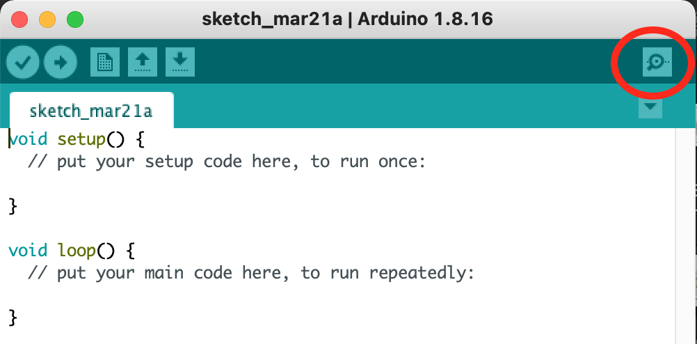
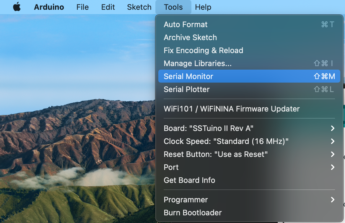
After the code has been uploaded to the SSTuino, let's head to the serial monitor of the Arduino IDE:
Here is how the circuit looks like:
Control your lights
This time with coding! 😁 With the data we have read from the push button, we can use it to trigger a reaction. Set up your circuit in TinkerCAD as shown:
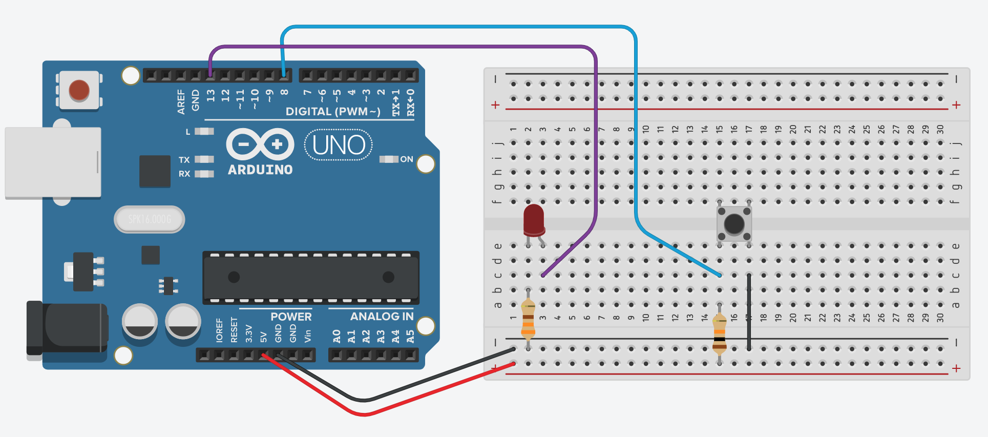
Next, we will need to edit the code such that the LED will light up when the button is pressed:
The block code is similar to the previous exercise, but with LEDs added this time. This will happen after you start simulation:
Let's copy this circuit over to your SSTuino! This is how it should look like:
Warning: To prevent damage to your Learning Device or your components, please do not connect the SSTuino to your LD or power supply when you are wiring up your circuit.
Let's share your work! Record and post a video onto Instagram with the hashtag #sstuino!