Programming the SSTuino II
Control your lights......This time with code!
In this tutorial, we will discuss the programming language that the SSTuino II uses, and explore some examples.
Table of Contents
Virtual Programming
Before we go into programming with the Arduino IDE, let us take things slow with the coding functionality on TinkerCAD!
The Arduino programming language is very similar to the C/C++ Language and are actually C/C++ functions that can be called into your code. When the code is uploaded onto the SSTuino, the compiler inside the Arduino IDE will convert it to something that the microcontroller can read. For documentation regarding the Arduino IDE, please visit this website.
Create a new circuit on TinkerCAD, and set it up like this:
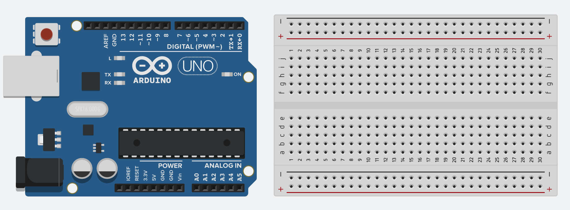
Once you set it up and press start simulation, notice the LED on the Arduino blinking? Why does this happen?
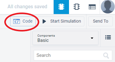
The reason this happens is that TinkerCAD automatically inserts a sample code when you add the Arduino into the circuit. Stop the simulation and press the Code button. You should see something like this:
TinkerCAD is very simple to use as you can use block coding to program the Arduino, and might be familiar if you have done block coding before with environments like Scratch or MIT App Inventor.
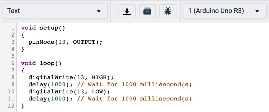
If you would like to program with text in TinkerCAD, you can also do so like this:
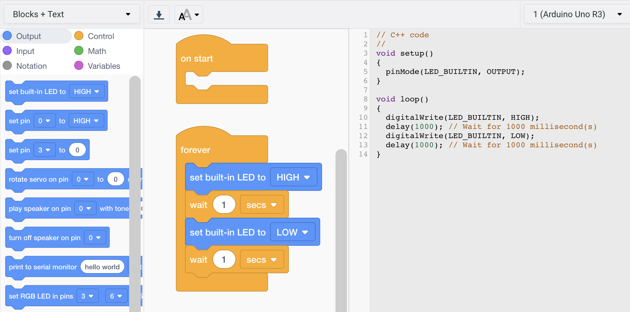
They also have another format called Blocks + Code. The text code changes according to the blocks that you place.
On Start, Forever
There are 2 main code block segments when you program your device. The first one is On Start, which is run only once when the device first starts up. The second one is Forever, which is always running in a loop (running over and over again) until the device is unplugged from power.
Tip: TinkerCAD will delete your blocks if you switch over to text-based programming and vice versa (i.e. your text programming will be deleted if you switch back to block based programming). 
So what does this block of code do? It tells the Arduino to:
- Turn on the built-in LED for 1 second,
- Turn off the built-in LED for 1 second
and it repeats all over until you turn off the circuit by unplugging the Arduino from the power source. In Arduino programming, HIGH means to turn something on or give it power, while LOW means to turn something off or to not give it power. For this code, there are only 2 states, HIGH or LOW. This means that it is either on or off and there is no value in between (either 1 or 0).
Now change the value of the wait ___ seconds to something that you like. What happens then?
Pin 13
Now, let us connect up this circuit:
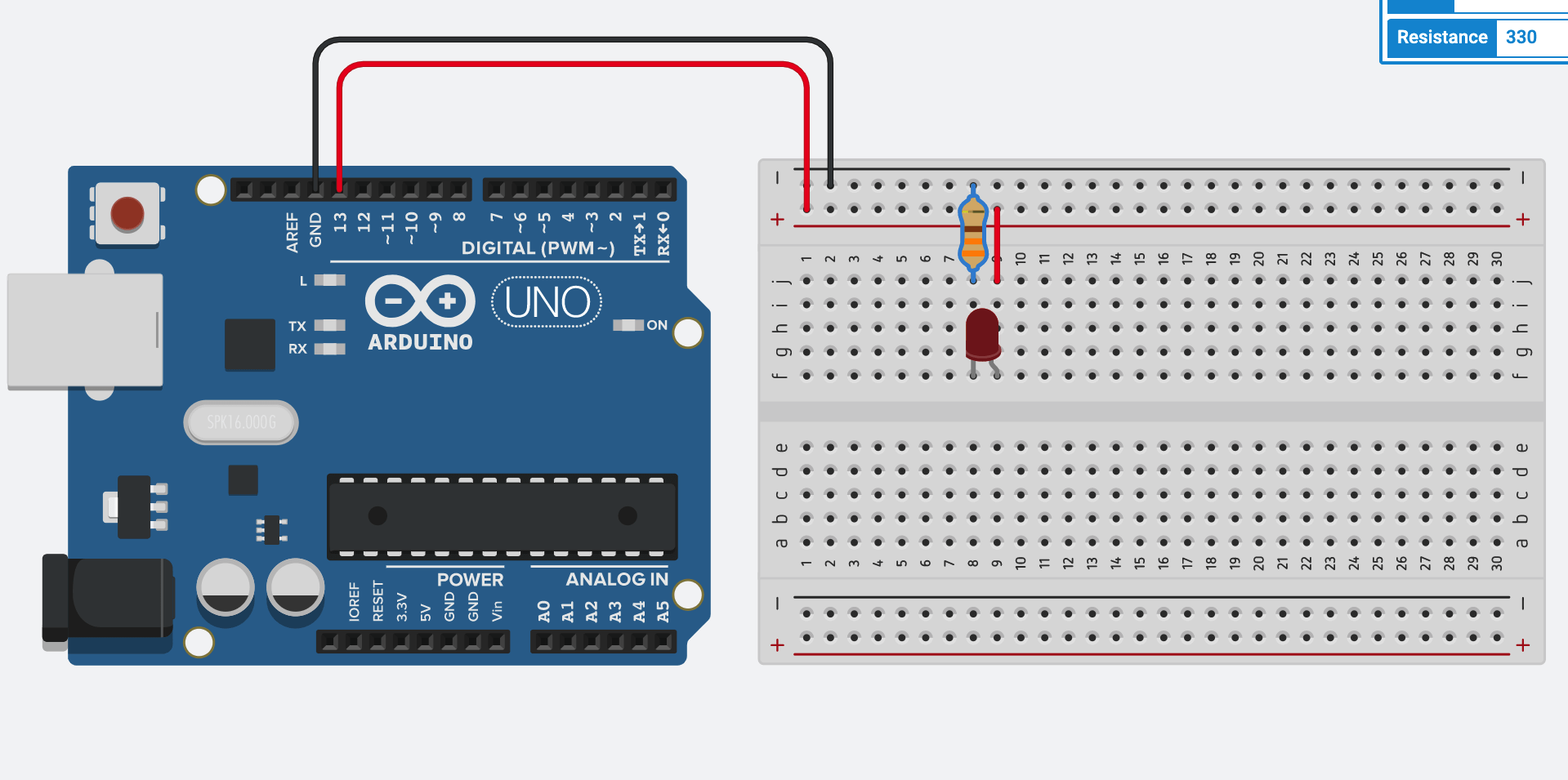
After you start the simulation, it should look something like this:
Wait a minute... How come the LED attached turns on and off even though I did not program it? Well, the reason behind it is that the built in LED on the Arduino board is also connected to pin 13. This means in the program, LED_BUILTIN is also pin 13.
Tip: For the Arduino Uno in TinkerCAD, the LED_BUILTIN LED pin is the same as pin 13. On the SSTuino II, the LED_BUILTIN LED pin and pin 13 are separate. The SSTuino II has more pins available than the Arduino Uno, so we assigned these 2 pins separately. This means that pin 13 does not affect the LED_BUILTIN LED!
Transfer program from TinkerCAD to Arduino IDE
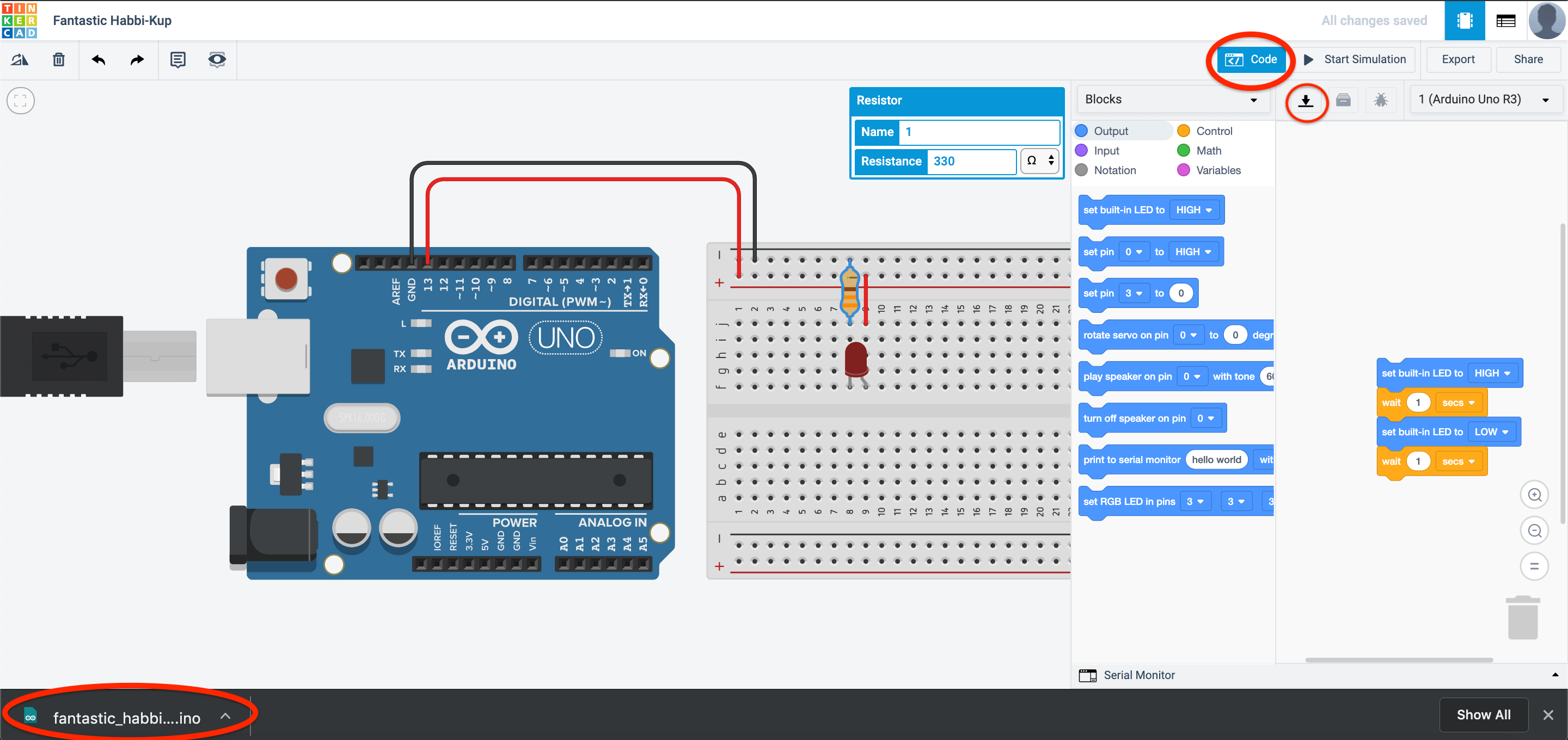
In TinkerCAD, another awesome feature is the ability to download the program that you have coded just now! Go to code, and press the download button:
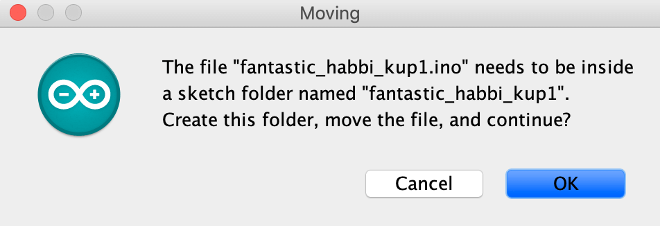
A .ino file will be downloaded on your LD and can be used on the Arduino IDE. Open the file and you would see a pop-up message. Click on ok. A folder will be generated and you will see the code appear in the Arduino IDE.
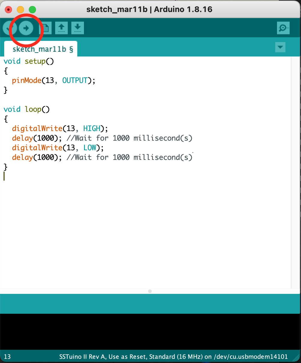
The Arduino app that you are using right now is called an Integrated Development Environment or IDE. It is one of the programs that you can program your SSTuino II in. Let us analyse the code we see here:
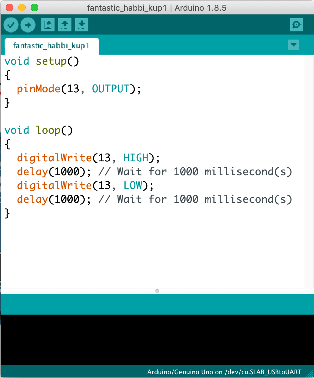
Here is an explanation of how most basic Arduino code works:
// These two slashes indicate a comment
/* This also indicates a comment
The brackets () indicate a function e.g. int main()
*/
void setup() //This is only run once when the device first powers up.
{ //<- The curly brackets are very important. Place them carefully to avoid confusion.
    pinMode(13, OUTPUT);
    /*
    Why is pinMode written as so? That is due to the practice of using camelCase for writing code.
    We declare pin 13 as the output pin. It can also be written as pinMode(LED_BUILTIN, OUTPUT).
    The state "OUTPUT" must be written in CAPITAL LETTERS.

    It is also very important to place a semicolon ";" when you finish your "sentence", just like
    how you write sentences in your essays.
    */

}

void loop() //loop = runs forever till the end of time (or until you turn off the power)
{
  digitalWrite(13, HIGH);// Turn on pin 13
  delay(1000); // Wait for 1000 millisecond(s)
  digitalWrite(13, LOW);// Turn off pin 13
  delay(1000); // Wait for 1000 millisecond(s)

  /*
  The section above will turn on and off the LED. Note the CAPITAL LETTERS on the "HIGH" and "LOW"
  */
}
Uploading code from Arduino IDE to SSTuino II
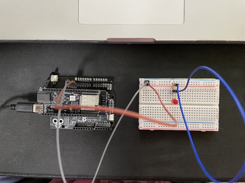
Let us connect our SSTuino like this:
Warning: To prevent damage to your Learning Device or your components, please do not connect the SSTuino to your LD or power supply when you are wiring up your circuit.
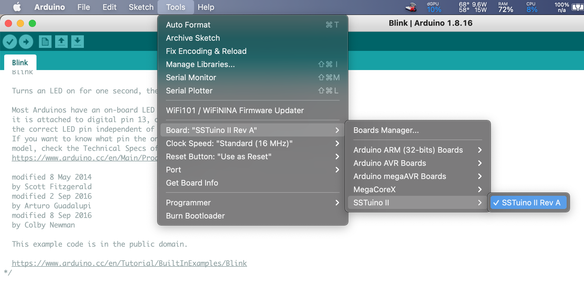
In your Arduino IDE, we will need to configure it to upload code to the SSTuino II.
- Plug in the SSTuino II into your LD
- Select the SSTuino II from
- Tools > Board > SSTuino II > SSTuino II Rev A
- Select the correct port:
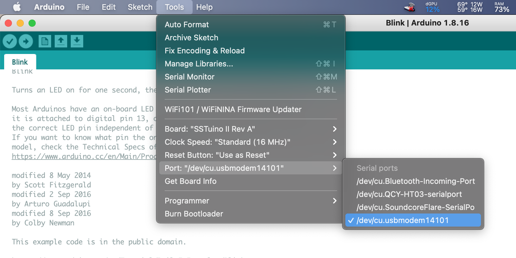
- Upload your code with this button
You should see your circuit light up like this:
With this example, we can see that the built-in LED for the SSTuino II is different from the Arduino Uno in TinkerCAD.
The explorer board has a cool feature to help to see if you have connection issues in your circuit!
For this particular example, if I connect the LED incorrectly (e.g. wrong LED polarity), you will notice that the LED on the Explorer Board lights up, but not the LED on the breadboard. I can use this information to diagnose what went wrong with the circuit, instead of wondering if I made a mistake on the circuit or in the programming instead.
Built-in LED
If you would like to use the built-in LED on the SSTuino II, you can always do so. Here is a basic example on the Arduino IDE to get you started. Go to:
File > Examples > 01. Basic > Blink
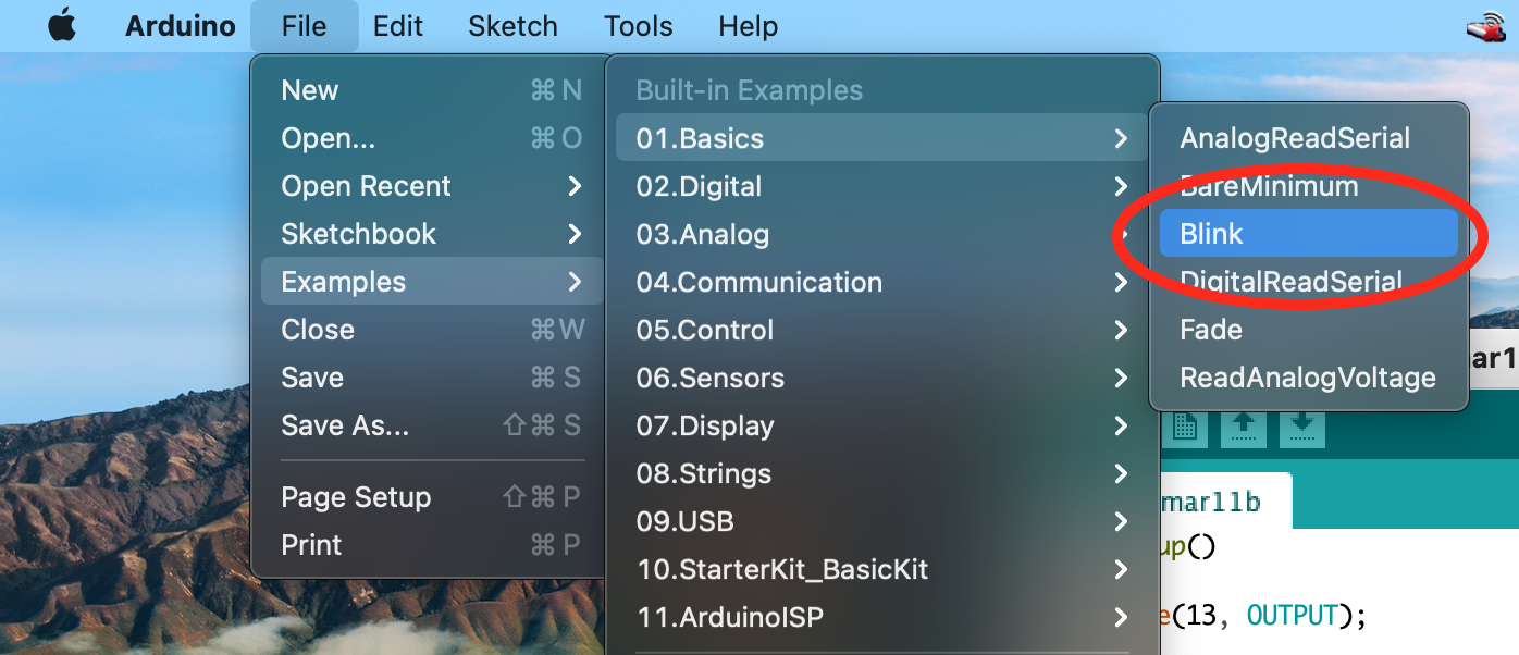
Plug in your SSTuino II and upload the code. You should see this on the SSTuino II. The Built-in LED on the SSTuino II lights up but not the LED at Pin 13.
Tip: Please note that the built-in LED and Pin 13 on the SSTuino II are different pins. 🙂